
|
Marine systems simulation
|
|
|
Marine systems simulation
|
 Collaboration diagram for Propeller:
This models an open water diagram based propeller in for FhSim. The propeller model is based on standardized one quadrant open/water test data for a single pitch and density ratio. The standard open water diagram only contains data for the first quadrant of propeller operational scenarios defined by the direction of incoming water flow and the direction of rotation of the propeller. The first quadrant open-water diagram contains propeller characteristics for forward thrust propeller rotation direction and incoming water flow from corresponding to an ship with forward positive speed. The pitch/density (PD) ratio determines the steepness of the propeller blades relative to the incoming flow. The model allow for several open-water diagrams obtained at different PD ratios to emulate a controllable pitch propeller where the actual PD ratio can be varied during operation.The FhSim open-water propeller model is a functional model which calculates the current thrust and torque from the current propeller rotational speed \(n\) and PD ratio.
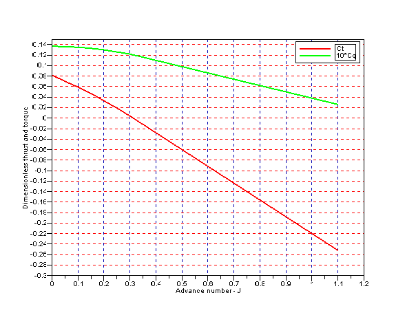
The open-water diagram contains information about the thrust and torque made non-dimensional by the following relationships
\[ C_t=\frac{T}{\rho \cdot n^2 \cdot D^4} \]
\[ C_q=\frac{Q}{\rho \cdot n^2 \cdot D^5} \]
Where \(T\) is the thrust of the propeller \(Q\)is the moment required to turn the propeller in the fluid, \(n\) is the revolutions pr second and \(D\) is the diameter of the propeller. The open water diagram contains \(C_t\) and \(C_q\) is a function of the advance number \(J\) which is defined as
\[ J=\frac{V_A}{n \cdot D} \]
Where \(V_A\) is the incoming flow velocity in the propellers axial direction. An example of a open-water diagram is shown in the figure below.
The thrust and torque are computed by calculating the current advance number based on the rotational speed of the propeller and the velocity component along its main axis. The \(C_t\) and \(C_q\) values are found by interpolation both by advance number and by PD ratio. The data input is controlled by the \(J\) and \(PD\) parameters which establish the two variable functions \(C_t=f_1(J,PD)\) and \(C_q=f_2(J,PD)\). The contents of the functions are provided by the \(C_t\) and \(C_q\) parameters respectively and take the form of matrices of size \(N_J \cdot N_{PD}\). The row of the matrix is delimited by ";" as seen in the input example below.
The propeller model also calculates the induced flow velocity in the jet behind the propeller as well as the radius of the propeller jet stream. The induced velocity and the spatial form of the jet stream is communicated to the sea environment to allow other objects to observe the increase in water velocity behind the propeller. The induced velocity and contraction of the propeller jet stream is calculated from the thrust loading coefficient \(C_T\)
\[ C_T = \frac{F}{\frac{1}{2}*\rho U^2 \pi r^2 }\]
And the induced flow velocity \(U_s\) is calculated form the thrust loading coefficient
\[ U_s = V_A \cdot \sqrt(1+C_T) \]
And finally the radius of the propeller jet stream
\[ r_s = r_{propeller} \cdot \sqrt( 0.5 + V_A/U_s) \]
The definition of the induced flow velocity \(U_s\) and the jet contraction \(r_s\) is shown in the figure below.
| Name | Width | Description |
|---|---|---|
| ForceDirectionNED | 3 | |
| VelocityNED | 3 | |
| PositionNED | 3 | |
| N | 1 | |
| PD | 1 | |
| PropellerForceBODY | 1 | |
| PropellerTorqueBODY | 1 |
| Name | Width | Description |
|---|---|---|
| ForceNED | 3 |
The force produced by the propeller in nort-east-down coordinates |
| TorqueNED | 3 |
The torque prodused by the propeller in nort-east-down coordinates |
| Us | 1 |
The propeller induced velocity on the water particle traveling through the propeller disk in m/s |
| Rs | 1 |
The radius of the propeller downstream jet in meters |
| BladeTopNED | 3 |
The top point of the propeller blade in north-east-down coordinates |
| Name | Width | Description |
|---|---|---|
| Diameter | 1 | |
| DummyPropeller | 1 | |
| PD | \(N_{PD}\) | List of PD ratios in the data set |
| J | \(N_{J}\) | List of advance numbers in the data set |
| Ct | \(N_{J} \cdot N_{PD}\) | Matrix of \(C_t\) values |
| Cq | \(N_{J} \cdot N_{PD}\) | Matrix of \(C_q\) values |
| Material | 1 | The material used to draw the propeller in the visualization |